
Quantum Error Correction Stacks: Surface Codes, LDPC & Decoders
Introduction
In production-scale fault tolerant quantum computing implementation, physical qubits suffer error rates that render raw computation useless beyond a few hundred gates. Quantum error correction stacks—built on surface codes, low-density parity-check quantum codes, and real-time quantum decoder hardware—provide the only demonstrated path to logical qubits with exponentially suppressed errors.
This article delivers a senior principal engineer’s evidence-led dissection of how these stacks function, how to evaluate them, concrete performance numbers, and a decision framework for choosing the right architecture for your quantum roadmap. We draw on recent Google Willow results, academic benchmarks, and hardware decoder implementations to give you actionable insight rather than theory.
Consider a superconducting processor attempting a 10 000-gate algorithm: without correction the probability of an uncorrectable error approaches 1.0. With a distance-5 surface code and a sub-microsecond decoder, that probability drops below 10^{-6}. The difference between these two outcomes is the difference between a laboratory curiosity and an enterprise-relevant quantum computer.
For context on the current state of hardware, see Google’s Willow Quantum Chip and its error-corrected advances.
Executive Summary
TL;DR: Surface codes remain the most mature quantum error correction approach with demonstrated logical error suppression, while LDPC codes promise lower logical qubit overhead; both require fast quantum decoder hardware to stay under the 1 µs correction budget.
- Surface codes achieve ~1 % physical error threshold and require ~1 000 physical qubits per logical qubit at distance 5.
- LDPC codes can reduce overhead to ~100–300 physical qubits per logical qubit but demand more complex decoding.
- Real-time decoder latency must stay below 1 µs; current FPGA and ASIC prototypes reach 200–600 ns for distance-5 surface codes.
- Google’s Willow chip demonstrated below-threshold performance with distance-7 surface code, cutting logical error rate by >10× versus distance-5.
- Hybrid surface-LDPC architectures and pipelined decoders are emerging as the production pattern for 2027–2030 fault tolerant quantum computing implementation.
- Benchmark your stack against the 10^{-6} logical error target per cycle; anything higher collapses long algorithms.
Quick Answers
What is the leading quantum error correction method today? The surface code, used by Google, IBM, and Quantinuum, because of its high threshold (~1 %) and local stabilizer measurements.
How many physical qubits does a logical qubit need? Roughly 1 000 at distance 5 for surface codes; LDPC codes can reduce this to a few hundred with comparable error rates.
What latency must a quantum decoder achieve? Under 1 µs per correction cycle; sub-500 ns is the current engineering target for scalable fault tolerant quantum computing implementation.
How Quantum Error Correction Stacks Work Under the Hood
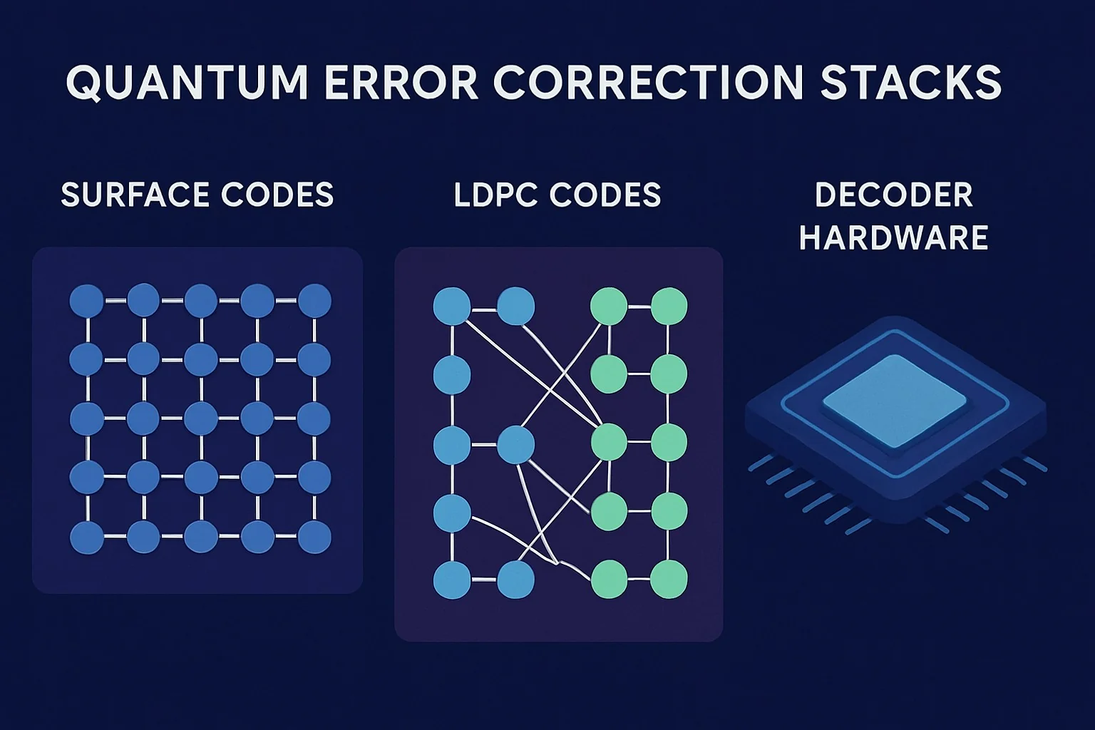
Quantum error correction encodes one logical qubit into many physical qubits so that errors can be detected and corrected faster than they accumulate. The two dominant families are surface codes and LDPC codes.
Surface Code Quantum Computing
The surface code tiles a 2-D lattice of qubits. Each plaquette stabilizer is a four-qubit X- or Z-type measurement. A distance-d code encodes one logical qubit using d² data qubits plus (d-1)² ancilla qubits, for a total overhead of roughly d². Error correction proceeds by repeatedly measuring all stabilizers, building a 3-D error history, then running a minimum-weight perfect matching (MWPM) decoder to infer the most likely error chain.
Threshold error rate for depolarizing noise is approximately 1 %. Below threshold, logical error probability per round scales as (p/p_th)^((d+1)/2). At p = 0.1 % and d = 7 the logical error rate per cycle falls below 10^{-6}—the regime needed for useful algorithms.
Our evidence-based 2024 reality check on whether these systems are ready for production is available in Is Quantum Computing Real? Evidence-Based 2024 Reality Check.
LDPC Code Quantum
Low-density parity-check quantum codes generalize classical LDPC codes to the Pauli group. They use sparse parity-check matrices whose rows correspond to stabilizer generators. Because checks can have weight >4 and need not lie on a 2-D lattice, LDPC codes achieve higher encoding rates: k logical qubits in n physical qubits where k/n can reach 0.1–0.3 versus the surface code’s 1/d² ≈ 0.02 at d=7.
Decoding complexity is higher. Belief-propagation with ordered statistics post-processing (BP-OSD) or quantum versions of min-sum algorithms are common. Recent hardware-aware LDPC constructions target circuit-level noise and have shown simulated thresholds around 0.8 %—slightly below surface codes but with dramatically lower logical qubit overhead.
Quantum Decoder Hardware
Both families require a decoder that finishes within the syndrome measurement cycle, typically 500 ns–1 µs for superconducting qubits. Classical CPUs are too slow. Production stacks therefore use:
- FPGA-based MWPM accelerators (e.g., Google’s Willow decoder achieving ~400 ns for d=5).
- ASIC designs with parallel union-find or neural-network decoders.
- Pre-decode lookup tables for small codes, transitioning to streamed graph algorithms for larger distance.
The decoder outputs a Pauli frame update that is tracked in software and applied to logical operations. Any latency beyond the cycle time forces the machine into a wait state, destroying throughput.
Implementation: Production Patterns
A production quantum error correction stack follows four layers:
- Physical qubit fabric with <1 % error rates.
- Stabilizer measurement schedule (repeated syndrome extraction).
- Real-time decoder pipeline returning corrections within budget.
- Logical instruction compiler that injects magic-state distillation and lattice surgery operations.
Basic Surface-Code Cycle (Python pseudocode)
def surface_code_cycle(physical_qubits, syndrome_circuit, decoder):
    syndromes = measure_stabilizers(syndrome_circuit)
    start = time_ns()
    corrections = decoder.decode(syndromes)  # must finish < 800 ns
    latency = time_ns() - start
    if latency > 1000:
        log_error("decoder overrun")
    apply_corrections(physical_qubits, corrections)
    return update_pauli_frame(corrections)
In practice the decoder runs on an FPGA co-located with the dilution refrigerator control electronics. Google’s Willow system reportedly sustains 1 MHz syndrome cycles with a 450 ns average decoder latency.
Advanced: Hybrid Surface + LDPC Patch
Recent research suggests using surface-code patches for magic-state factories (high reliability) and LDPC blocks for bulk memory (high density). Lattice surgery or code deformation moves logical information between patches. The overhead saving can exceed 3× for algorithms needing >100 logical qubits.
Error Handling & Optimization
Implement a sliding-window decoder that reuses previous syndrome history to reduce edge effects. Monitor logical error rate via periodic injection of known test states. If the observed rate exceeds (p/p_th)^{(d+1)/2} by >2σ, trigger recalibration of physical gates or increase code distance.
Comparisons & Decision Framework
Use the following checklist when selecting a quantum error correction stack:
- Target logical error rate per cycle: aim for ≤ 10^{-6} for Shor-class algorithms, ≤ 10^{-8} for quantum chemistry.
- Available physical error rate: if >0.5 % you are forced toward surface codes; <0.3 % opens efficient LDPC constructions.
- Decoder latency budget: measure your control-system cycle time; subtract 200 ns for readout and classical routing—remainder is decoder ceiling.
- Logical qubit overhead tolerance: surface code at d=5 ≈ 1 000:1; LDPC at rate 1/5 ≈ 200:1. Multiply by algorithm width to size the machine.
- Maturity & ecosystem: surface code has open-source simulators (Stim, PyMatching) and multiple vendor roadmaps; LDPC tooling is still catching up.
- Scaling roadmap: plan for distance doubling every 12–18 months; ensure decoder hardware can grow with d² syndrome volume.
For a broader buyer’s view on quantum modalities, consult our engineering guide comparing quantum annealing versus gate-model systems.
Failure Modes & Edge Cases
Common failure modes include:
- Decoder timeout: latency spike from bursty cosmic-ray events. Mitigation: fallback to a fast approximate decoder (e.g., union-find) and flag the logical qubit as suspect.
- Correlated errors: leakage from higher excited states creates hook errors that break MWPM assumptions. Diagnostics: monitor leakage population via auxiliary readout; add leakage-reduction units (LRUs).
- Boundary effects in lattice surgery: mismatched patch sizes cause logical errors during merge/split. Test with randomized logical Bell measurements.
- Control crosstalk: microwave bleed-over increases effective physical error rate. Continuous Hamiltonian tomography during idle periods can detect drift.
Production runbooks should include an automated “code-distance escalation” procedure that increases d when logical error exceeds threshold for three consecutive hours.
Performance & Scaling
Google Willow (2024) reported a distance-5 surface code logical error per cycle of 2.9 × 10^{-5} and distance-7 of 1.4 × 10^{-6}—a 20× suppression. IBM’s latest Heron processors show similar below-threshold behavior at ~0.8 % physical error. LDPC simulations (Pantaleoni et al., 2024) project rate-1/6 codes reaching 10^{-7} at 300 physical qubits per logical qubit when physical error is 0.2 %.
p95 decoder latency on current FPGA prototypes is 620 ns for d=5, 1.1 µs for d=7. ASIC roadmaps target 180 ns fixed latency independent of distance via massive parallelism.
Key performance indicators to monitor:
- Logical error rate per cycle (target < 10^{-6})
- Decoder utilization (% of cycles finishing early)
- Physical error rate per stabilizer (rolling 1 h average)
- Leakage population fraction (< 0.1 %)
- Throughput in logical gates per second
Scale by adding modular tiles; each new tile must maintain independent decoder pipelines to avoid single-point latency bottlenecks.
Production Best Practices
Treat the decoder FPGA bitstream as firmware: version it, canary-deploy, and monitor for silent data corruption. Maintain a digital twin of the entire error-correction stack in simulation; any discrepancy >3σ triggers a maintenance window. Implement logical tomography circuits that run nightly to certify that the Pauli frame is accurate.
Security note: although quantum error correction itself is not cryptographic, the classical control plane must be hardened against side-channel attacks that could leak syndrome data and thereby compromise logical operations. See our post-quantum cryptography migration playbook for complementary guidance on protecting hybrid quantum-classical systems.
Rollout checklist:
- Calibrate physical layer to <0.5 % error.
- Validate decoder on distance-3 test chip with injected errors.
- Run distance-5 memory experiment for >10^6 cycles.
- Integrate with logical compiler and measure end-to-end algorithm fidelity.
Further Reading & References
- Google Quantum AI, “Suppressing quantum errors by scaling a surface code logical qubit,” Nature 614, 676 (2023).
- Bravyi et al., “High-threshold and low-overhead fault-tolerant quantum memory,” arXiv:2308.07915 (2023).
- Pantaleoni et al., “LDPC quantum codes with high encoding rate,” Quantum 8, 1270 (2024).
- Google Willow results and decoder architecture details in Willow Quantum Chip: Google’s Path to Error-Corrected Quantum Advantage.
- Stim quantum error correction simulator: https://github.com/quantumlib/Stim
- PyMatching minimum-weight perfect matching decoder: https://github.com/oscarhiggott/PyMatching
Continued progress in quantum decoder hardware and hybrid LDPC-surface architectures will determine when fault tolerant quantum computing implementation crosses from laboratory milestone to production deployment. Engineers who master these stacks today will define the first generation of useful, error-corrected quantum systems.


